
What is Winding Process?
Winding is performed to transform small ring frame package “cop” into a bigger package suitable for production of warper’s beam for weaving. The winding process achieves the twin objectives of reducing the imperfections in the ring yarn as well as converting it into bibber package in the form of cone/ cheese. The winding process gives an opportunity to clear the yarn from its defects. During rewinding, the yarn is cut at the faulty places and rejoined either by knotting or splicing. During winding process, many yarn faults (thick place, slubs, thin place, etc.) are also removed.
Winding Machine:
In most winding machines, the spinning bobbins are mounted in an approximately vertical position below the winding unit. The yarn is withdrawn over the top end of the spinning bobbin, moves through yarn guides, tensioning devices, and slub catchers before winding onto the core, the tensioning device is set to establish the correct density or firmness of the package, while the slub catchers serve to catch and break out slubs, large knots, and wild or kinky yarn.
Types of Winding Machine:
There are different types of winding machine. Winding machine categorized in various way. These are given below.
On the basis of winding:
On the basis of winding, winding machines can be classified into two groups:
- Precision winding
- Non-precision winding
On the basis of package type:
On the basis of package type, winding machines can be classified into at least five groups as given below:
- Cope winding machines
- Cone winding machines
- Cheese winding machines
- Flanged bobbin winding machines
- Pirn winding machines
On the basis of package drive:
- Direct drive winding machines
- Indirect drive winding machines
On the basis of yarn type:
- Warp yarn winding machines
- Upright spindle winding machine
- Drum winding machine
- Weft yarn winding machines
- Pirn winding machines
- Ordinary pirn winding machines
- Automatic pirn winding machines
- Cope winding machines
- Pirn winding machines
Important Parts of Winding Machine:
The winding machine consists essentially of the following parts:
- The winding drum
- Yarn clearers
- Supply system
- Stop motion
- Tensioner
Schematic diagram and parts of winding machine is shown in Figure 1.
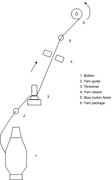
The yarn from the supply package passes through the tension device, yarn clearing unit, stop motion and onto the rotary traverse winding drum. When the winding drum is driven by the motor the take-up package rotates by friction drawing the yarn from the supply package. Whenever a yarn fault, such as thick places, snarls etc., is detected by the clearing unit, the yarn is cut at that place, and the yarn is again rejoined. Thin places also will be removed, because the yarn will break at that place due to tension, and rejoined again. Hence, the majority of the yarn faults will be removed by the winding process.
1. The Winding Drum:
The winding drum is a cylindrical grooved metallic or bakelite drum that rotates the take up package by frictional contact. All the high-speed winders adopt the negative friction drive as it is mechanically less complex. The groove in the drum gives traverse movement to the yarn, which lays the yarn throughout the width of the package. This groove arrangement eliminates the necessity for a separate traverse mechanism. The angle of the groove in relation to the drum axis determines the angle of wind on the yarn package. The normal range of angle of wind is from 30° to 55°. As the angle of wind increases the density of the package will degrease. The conicity of the package will vary from 5°57′ to 9°15′ depending on the requirement.
The drums are normally made with 1.0, 1.5, 2.0 and 2.5 scroll. For a 2.5 scroll, the drum makes 2.5 revolutions for one complete traverse, and this corresponds to the minimum angle of wind and maximum density.
2. Yarn Clearers:
The process of removing the thin, thick places and objectionable faults is called yarn clearing.
There are two types of yarn clearers:
- Mechanical yarn clearer
- Electronic yarn clearer
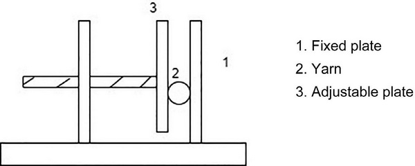
The mechanical yarn clearer, called slub catchers, consists of two plates separated by a gap as shown in Figure 2. This gap can be adjusted according to the requirements by moving the adjustable plate. The yarn passes through the gap between the plates. Whenever a yarn fault having thickness more than the size of the gap enters the gap, it cannot pass through the gap, and hence, the yarn is broken at that place and a knot is put.
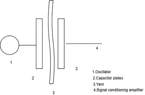
The electronic yarn clearer consists of a capacitor having two plates as shown in Figure 3. The yarn is passed through the plates. The capacitance of the plates varies whenever the yarn thickness varies. The variation in the capacitance is measured and fed into the controlling unit, and whenever the variation exceeds the predetermined limit, the control unit actuates a cutter, and the cutter cuts the yarn.
The faulty section of the yarn is removed either manually or by air suction; then, the yarn ends are joined by a knot.
3. Supply System:
The supply section consists of a bobbin holder and a yarn guide. In automatic winding machines, the bobbin holder will accommodate six or more number of bobbins.
4. Stop Motion:
Stop motion is used to stop the winding whenever yarn is broken. This may be mechanical or electronically controlled.
5. Tensioners:
A tensioner is provided to give tension to the yarn. There are two types of tensioners: One type is a disc type, and the other is a friction type. In the disc-type tensioner, the yarn passes between two discs. The tension is adjusted by means of adding additional weights on the top disc. In the friction-type tensioner, the tension is adjusted by changing the angle of contact between the yarn and the friction imparting element
References:
- Fabric Manufacturing Technology: Weaving and Knitting by K. Thangamani and S. Sundaresan
- Industrial Practices in Weaving Preparatory By Dr Mukesh Kumar Singh
- Weaving Preparation Technology By Dr. N. Gokarneshan