What is Shedding Mechanism in Weaving?
The fundamental weaving principles and operation of a loom includes shedding, picking, beat-up, let-off, and take-up. Among those shedding is the most important. The shedding mechanism separates the warp yarns into an upper and lower layer, allowing a weft yarn to be inserted. Shedding is an important motion in weaving operation. Without shedding weaving cannot be done. All designs are created only by a shedding motion. The properties of the final fabrics, to a larger extent, depend on the shedding. There are three types of shedding systems available for the formation of warp shed in weaving machines:
- Tappet or cam shedding mechanism
- Dobby shedding mechanism
- Jacquard shedding mechanism
The cam and dobby shedding mechanisms control the heald frames and each heald frame controls a group of warp threads. The maximum no of heald frames possible in a cam shedding is eight. Hence, only weave patterns having a repeat of less than eight warp threads are possible to weave in cam shedding. This limitation is due to the design of the cam. Up to 24 heald frames can be accommodated in a dobby shedding. Therefore, weave patterns having a repeat of up to 24 warp threads can be woven in dobby shedding. Warp threads are controlled individually in jacquard shedding. The limitation for the number of warp threads in a repeat in jacquard shedding is the capacity of the jacquard, which is usually 400,800 or 1600 hooks.
A. Tappet Or Cam Shedding Mechanism:
The tappet and/or cams shedding are the simplest mechanisms on power dobby weaving technologies and refer to the principle of operation by which a shed is formed by their use. A majority of weave pattern commonly used can be produced using cam shedding. The disadvantage of cam shedding is that whenever the weave pattern is changed, it becomes necessary to rearrange the cams, which is a time-consuming process.
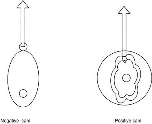
A cam is a disk that transforms the rotational motion into the reciprocating motion of the follower. The transfer is done by means of the cam’s edge, in the ease of a negative cam, and by means of a groove cut in the side surface of the cam, in the case of a positive cam. Figure 1 illustrates negative and positive cams.
1. Negative cam shedding:
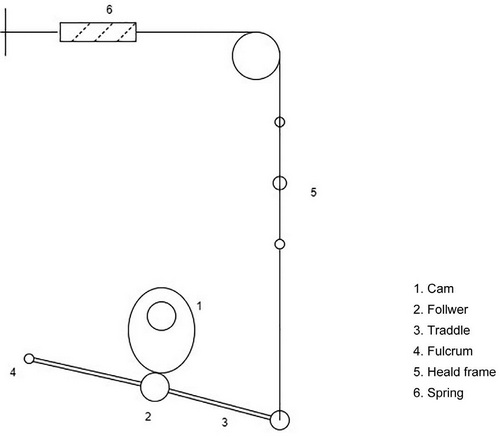
The negative cam mechanism acts only in one direction. It either raises or lowers the heald frames. A reversing mechanism is necessary to return the heald frames. A spring reversing motion is used in most cases. Figure 2 illustrates the action of negative cam shedding. As cam 1 rotates, it presses follower 2 downwards. This will make traddle 3 to pull heald frames 5 downwards against the action of spring 6. As the cam rotates further, the edge of the cam moves up paving the way for the spring to lift the heald frames and the traddle.
2. Positive cam shedding:
The heald frames are raised and lowered by cams in the positive cam shedding. There are two types of positive cams. In the first, a roller follows a groove cut in the face of the cam. An ‘L’-shaped lever is attached to the roller, and when the roller moves up and down as the cam rotates the other end of the lever moves back and forth in a horizontal direction. This motion is carried to the heald frames through various levers.
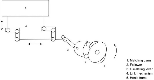
In the second type of positive cam shedding a pair of matched cams are used for each heald frame. The two rollers, which are in contact with cam faces, oscillate the lever to which they are attached. This oscillation is converted into an up-and-down movement of heald frames through levers. Figure 3 shows a positive cam system with two negative cams.
B. Dobby Shedding:
The term dobby is a component/mechanism attached to a loom to support the process of shaft movement. The dobby requires a cam mechanism to drive the dobby and control the movement of the shafts to produce the required shedding configuration. The combined dobby cam system permits the weaving of more complex woven textiles than the tappet and/cam alone and therefore a greater number of shafts, allowing for more complex combinations of weave architectures. Whenever the number of heald frames exceeds 8 a dobby mechanism is necessary for shedding. A dobby consists of two parts. The first part is a lifting mechanism to lift the heald frames, and the second part is a selection mechanism to select the healds to be lifted. There are two types of dobbies: (1) negative dobbies and (2) positive dobbies.
1. Negative dobby:
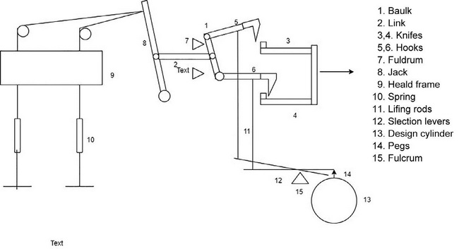
In a negative dobby, the heald frames are lifted by the dobby and lowered by spring motion. Figure 4 shows a schematic of a double lift negative dobby. Two knives, 3 and 4, with a pair of hooks, 5 and 6, are used to lift the heald frames 9 through baulk 1 and jack 8 while the heald frames are lowered by springs 10. Whenever peg 14 in the design cylinder 13 comes vertical under selection lever, the peg lifts selection lever 12, and the other end of the selection lever is lowered. This makes the lifting rod 11 come down slightly, which makes the lower hook also come down in the way of the lower knife. When the lower knife moves forward, this will pull the lower hook forward, and as a result, the baulk and jack are made to make an angular movement. This angular movement lifts the heald frames through strings. The pegs are pegged in the lag, and all the lags are joined to make a chain. Each lag corresponds to two picks.
In modern machines, as an alternative to lag-and-peg chains, punched paper or plastic pattern cards are used. A punched hole in the paper corresponds to a peg in the lag and this causes the corresponding heald frame to lift.
2. Positive dobby:
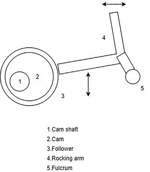
The heald frames are lifted and lowered both by the dobby mechanism. The need for the springs is eliminated. As a result, positive dobbies are capable of running at higher speeds. Rotary dobbies are good examples for positive dobbies. Figure 5 shows the working of rotary dobby. As cam 2 rotates along with cam shaft 1, it produces a rocking movement in rocking arm 4. As the rocking arm makes an angular movement, the other end makes a traverse movement. This is used to lift and lower the heald frames through a linking mechanism.
C. Jacquard Shedding:
The first jacquard machine was invented by Joseph Marie Jacquard (1752–1834). Jacquard shedding offers individual control of warp threads, and as a result, heald shafts are not required. They are simple in principle and construction, with unlimited patterning possibilities. Jacquard machines contain many parts, which are difficult to maintain. The jacquard shedding mechanism is dependent upon the type of compatible weaving machine it is connected to; the maximum total number of hooks/warp ends in the weaving width; the shuttle type employed for the weft insertion; and the required shedding geometry associated with the production of the woven textile: single layer; pile; leno; compound technical woven’s. Figure 6 shows the working principle of single-lift single-cylinder jacquard machine.
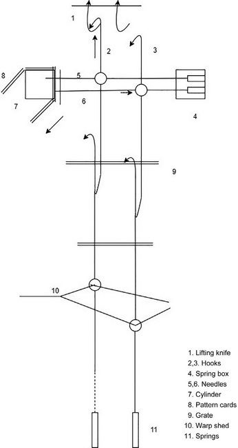
A jacquard machine consists of two parts: a selection mechanism and a lifting mechanism. The selection mechanism consists of needles 5, 6; spring box 4; pattern cards 8; and cylinder 7. The lifting mechanism consists of hooks 2, 3; knife 1; grate 9; and springs 11. The fabric design is punched in pattern cards, and each card represents one pick in the weave. There is one needle and one hook for every warp thread in the repeat. Pattern card 6 is presented to cylinder 7 in such a way that each card fits one side of the pattern cylinder. For every pick, the cylinder rotates and presses against the needles. The coil springs in spring box 4 also press the needles toward the cylinder. Suppose that a hole is there in the punched card against needle 5 and the needle will go inside the hole positioning hook 2 against knife 1. When the knife makes an upward movement, hook 1 will be lifted, making the warp thread attached to the hook to form the upper shed. If there is no hole in the card, as for the case of needle 6, the needle will be moved horizontally, making hook 3 defects away from the knife. The knife will not lift hook 3, making the warp thread attached with hook 3 form the bottom shed. After each pick, the cylinder is moved away from the needles, rotated and presented against the needles for the next pick.
The capacity of jacquard machine is indicated by the number of hooks, and each hook will control one warp thread. For example a 600-hook jacquard will control 600 warp threads. Single-lift jacquard machines are slow in operation. Therefore, modern weaving machines employ double-lift jacquard machines, which can run at higher speeds. A double-lift jacquard has two sets of knives that move up and down opposite to each other in a two-pick cycle. Electronically controlled double-lift jacquards are used in shuttleless weaving machines.
References:
- Fabric Manufacturing Technology: Weaving and Knitting by K. Thangamani and S. Sundaresan
- Textile and Clothing Design Technology Edited by Tom Cassidy and Parikshit Goswami
- Handbook on fabric manufacturing (grey fabrics: preparation, weaving to marketing) by B. Purushothama
- Principles of Fabric Formation By Prabir Kumar Banerjee
